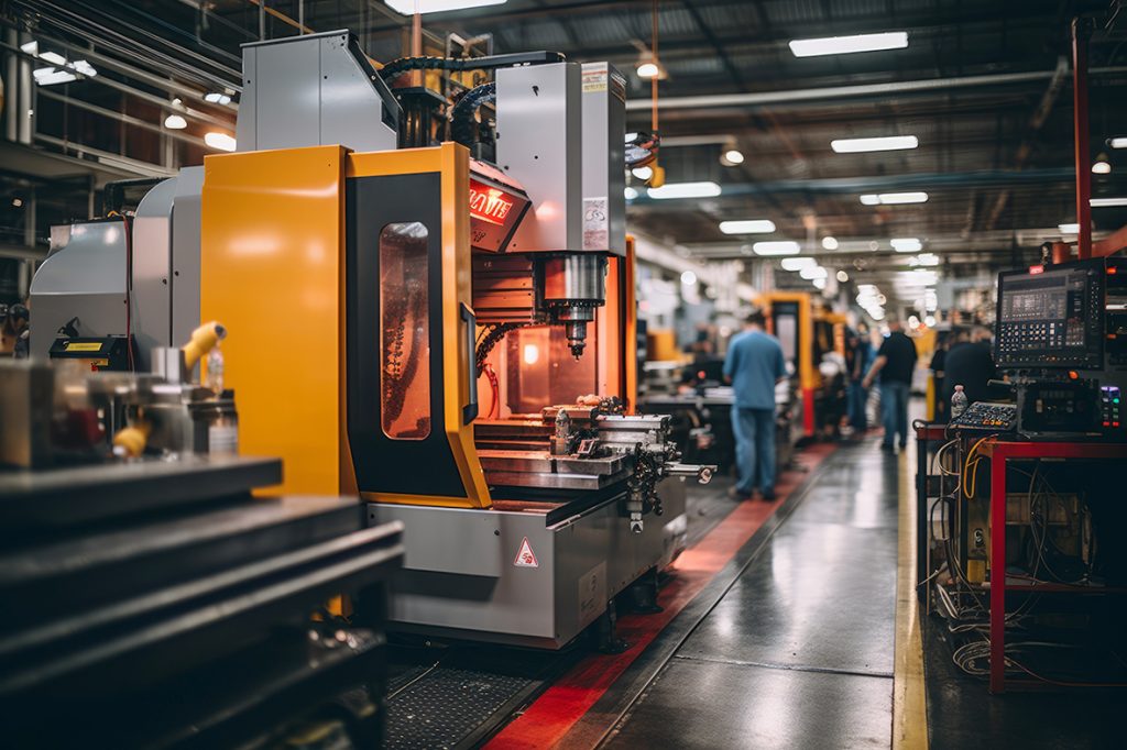
The machine tool spindle is a core component in mechanical processing, directly affecting machining accuracy, efficiency, and product quality. The primary function of the spindle is to drive the rotation of the tool or workpiece, enabling various machining operations such as cutting, grinding, and drilling. Modern machine tool spindle designs are diverse, classified based on different driving methods and application requirements into types like belt-driven, direct-drive, gear-driven, and built-in spindles. Each of these spindle types has its advantages and disadvantages, suitable for different machining conditions and needs.
Understanding the types and characteristics of spindles is crucial for selecting the appropriate machine tools and improving machining efficiency. For example, in high-precision machining, choosing a spindle with high rigidity and precision can significantly enhance machining performance; for heavy cutting, selecting a high-torque spindle ensures stability and efficiency. Each spindle type has different design philosophies and operating principles, with varying maintenance and usage costs. Therefore, selecting the appropriate spindle type based on actual machining requirements and economic conditions can effectively control costs, improve product quality, and maintain a competitive edge in the market.
Factors Affecting CNC Spindle Accuracy
In CNC machining, spindle accuracy plays a decisive role in product quality and efficiency. Any deviation in the spindle directly leads to dimensional errors, poor surface finish, shortened tool life, and reduced machine stability. The following are the key factors that influence spindle accuracy:
1. Spindle Design and Manufacturing Precision
The rigidity, concentricity, and dynamic balance of the spindle structure determine its stability during cutting. Even slight eccentricity or geometric errors during grinding and assembly may be amplified at the tool tip, resulting in dimensional inaccuracy. High-precision spindles are manufactured with ultra-fine grinding and balancing processes to ensure rotational accuracy.
2. Bearing Quality and Installation
Bearings are the heart of the spindle. High-speed machining centers often use angular contact ball bearings or hybrid ceramic bearings to withstand high speeds and cutting forces. Improper preload, poor lubrication, or uneven installation can cause runout and heat buildup, which lowers accuracy.
3. Thermal Deformation and Temperature Control
Heat generated during high-speed rotation causes thermal expansion of the spindle and bearings, resulting in axial or radial displacement. To minimize this effect, many spindles employ internal cooling systems, oil-air lubrication, and temperature compensation technologies to stabilize accuracy.
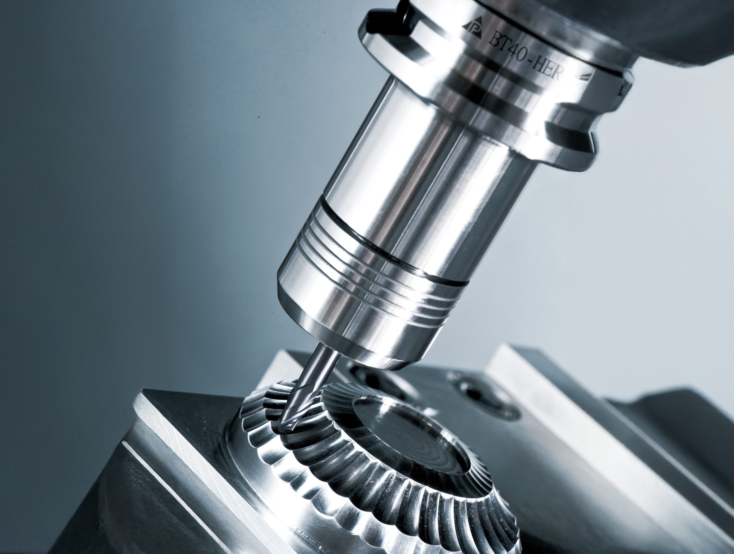
4. Toolholder and Clamping Rigidity
Even if the spindle itself is highly precise, insufficient rigidity in the toolholder (BT, HSK, hydraulic chucks, etc.) can lead to runout and machining errors. Especially in high-speed or heavy-duty cutting, toolholder balance and rigidity are crucial. Using precision toolholders and maintaining clean contact surfaces ensures consistent accuracy.
5. Cutting Load and Machining Conditions
Different cutting conditions apply varying loads to the spindle. Excessive cutting force or vibration can cause spindle deflection and accuracy loss. Proper cutting parameters (speed, feed rate, depth of cut) and tool selection reduce spindle stress and improve performance.
6. Maintenance and Usage
Over time, spindle bearings wear, lubricants degrade, and contamination may occur, all of which lower accuracy. Without regular inspection and maintenance, errors accumulate and machining quality deteriorates. Scheduled maintenance and vibration/temperature monitoring are essential for long-term precision.
In the following content, we will briefly introduce the four types of machine tool spindles: belt-driven, direct-drive, gear-driven, and built-in spindles, and analyze their respective advantages, disadvantages, and applicable scenarios. Through this information, we hope to help readers better understand the characteristics of machine tool spindles and make more informed decisions when selecting and using machine tools.
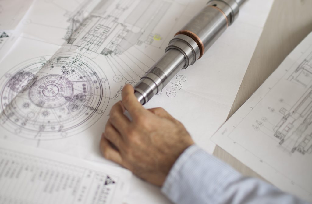
Introduction to spindle structure
Belt-Driven Spindle
The belt-driven spindle transmits power from the motor to the spindle via a belt, featuring a simple structure and low cost. The belt can absorb some mechanical vibrations, reducing the impact of vibrations during machining. However, due to the elasticity of the belt, power transmission efficiency is lower, and the spindle's speed and torque suffer some loss, making it suitable for workpieces with less demanding precision requirements.
The belt-driven spindle also has some drawbacks. Due to the belt's elasticity, power transmission efficiency is lower, leading to certain losses in the spindle's speed and torque, affecting machining efficiency and accuracy. The belt tends to wear out and needs regular replacement, increasing maintenance costs. Because of the belt's elastic properties, transmission accuracy is not high, so the belt-driven spindle is more suitable for workpieces with low precision requirements, such as light or medium mechanical processing.
Direct-Drive Spindle
The direct-drive spindle mounts the motor directly on the spindle, eliminating intermediate transmission components. This design provides extremely high speed and torque transmission accuracy, making it very suitable for high-precision and high-speed machining applications, such as aerospace and precision mold manufacturing.
With no intermediate transmission components, vibrations and noise during operation are reduced. This structure has a higher manufacturing cost as it requires high-precision manufacturing processes to ensure perfect integration between the motor and the spindle. High-speed operation tends to generate a lot of heat, requiring an efficient cooling system to maintain stability. Additionally, the maintenance and replacement of parts for direct-drive spindles are more challenging, with higher maintenance costs.
Gear-Driven Spindle
The gear-driven spindle transmits power from the motor to the spindle through a gearbox, providing high torque and stable speed, suitable for heavy cutting and large-scale processing, such as in automotive manufacturing and shipbuilding. The gears wear out during operation, generating noise and vibration, which affects machining quality, and requires regular lubrication and maintenance.
However, gears wear out during operation, producing noise and vibration, affecting machining quality. The gearbox requires regular lubrication and maintenance, increasing operating costs. The gear-driven spindle's structure is relatively complex, requiring professional technical support for manufacturing and repair, which also increases usage difficulty.
The gear-driven spindle is suitable for enterprises needing to handle heavy workpieces and mass production. Despite the high maintenance cost, its strong load capacity and operational stability make it irreplaceable in certain specific applications.
Built-In Spindle
The built-in spindle is a design where the motor is installed inside the spindle, forming an integrated structure. This design combines the high precision of the direct-drive spindle and the vibration damping characteristics of the belt-driven spindle, offering high rigidity and precision, suitable for high-end precision machining applications. The manufacturing cost for this design is extremely high due to the need for precise manufacturing processes and techniques to ensure perfect internal structure matching. The internal structure is complex, making maintenance and part replacement difficult, requiring high technical expertise, and costing more.
Additionally, high-speed operation generates a lot of heat, necessitating an efficient cooling system for stable operation. The built-in spindle is suitable for companies with extremely high requirements for machining precision and stability. Although the initial investment and maintenance costs are high, its excellent performance and high stability make it irreplaceable in high-end precision machining fields.
Comparison of spindle rigidity
Spindle rigidity is a key factor affecting machining accuracy and stability. A spindle with high rigidity can maintain stability during heavy load cutting, reducing deformation and vibration in the machining process, thereby improving machining quality. Different spindle types exhibit different rigidity performances:
Belt-Driven Spindle Due to the elasticity of the belt, rigidity is relatively low, suitable for light and medium mechanical processing.
Direct-Drive Spindle High rigidity, as the motor directly drives the spindle without the influence of intermediate transmission components.
Gear-Driven Spindle Highest rigidity, suitable for ultra-high precision machining applications.
Built-In Spindle : Highest rigidity, suitable for extremely high-precision machining applications.
Differences in spindle maintenance
Spindle maintenance is crucial for ensuring machining accuracy and extending service life. Different spindle types vary in maintenance difficulty and costs:
Belt-Driven Spindle: More difficult to repair and replace parts, with higher maintenance costs.
Direct-Drive Spindle: Requires regular lubrication and maintenance of gears, with a more complex structure and higher repair costs.
Gear-Driven Spindle:Requires regular lubrication and maintenance of gears, with a more complex structure and higher repair costs.
Built-In Spindle: Complex internal structure, difficult maintenance and part replacement, requiring high technical expertise and costing more.
Conclusion
Choosing a suitable machine tool spindle is crucial for processing enterprises. Each spindle design has its unique advantages and disadvantages and application scope. The belt-driven spindle is suitable for low-cost basic processing, the direct-drive spindle is suitable for high-precision and high-speed processing needs, the gear-driven spindle is suitable for heavy-duty cutting, and the built-in spindle stands out in high-end precision processing. Understanding the advantages and disadvantages of various spindles can help users make wiser decisions when choosing and using machine tools, improving processing efficiency and product quality.
Additionally, other types of spindle designs exist, such as hydraulic spindles, air hydrostatic spindles, and electromagnetic spindles. Hydraulic spindles are driven by a hydraulic system, offering high rigidity and stability, suitable for high-load, high-precision machining applications. Air hydrostatic spindles use an air film generated by compressed air to support and drive the spindle, providing extremely high rotational precision and low friction, ideal for ultra-precision machining. Electromagnetic spindles use electromagnetic forces to drive and support the spindle, featuring no friction, high speed, and high precision, suitable for ultra-high precision machining applications.
As technology advances, the design and manufacturing techniques of machine tool spindles continue to evolve, and new spindle designs may emerge in the future to meet different machining requirements. Understanding and mastering the latest spindle technologies are crucial for improving machining efficiency and competitiveness.