Understanding Surface Roughness: From Tactile Feel to Precise Measurement
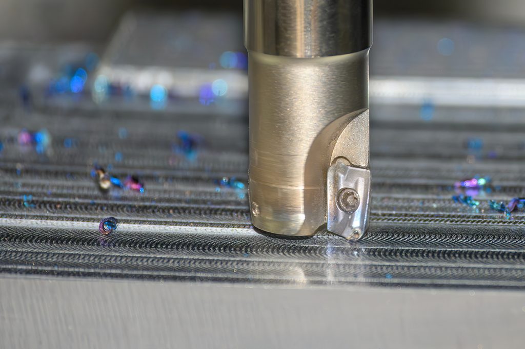
Surface roughness is a technical metric used to describe how smooth or textured a material’s surface is. While it may sound abstract, we encounter it in daily life — the coarse feel of a painted wall, the sleek touch of a smartphone screen, or the subtle difference in finish between two metal parts. In precision machining, surface roughness refers to the microscopic peaks and valleys left behind after manufacturing. These minute details can have a significant impact on a product’s performance, durability, and even its appearance. Understanding surface roughness is therefore the first step in assessing machining quality.
粗糙度怎麼表示?Ra / Rz / Ry 各是什麼意思?
In metalworking and quality inspection, surface roughness is a critical factor that influences assembly precision, operational performance, wear resistance, and product lifespan. While there are many ways to express roughness, three parameters are most widely used in both international standards and engineering practice:
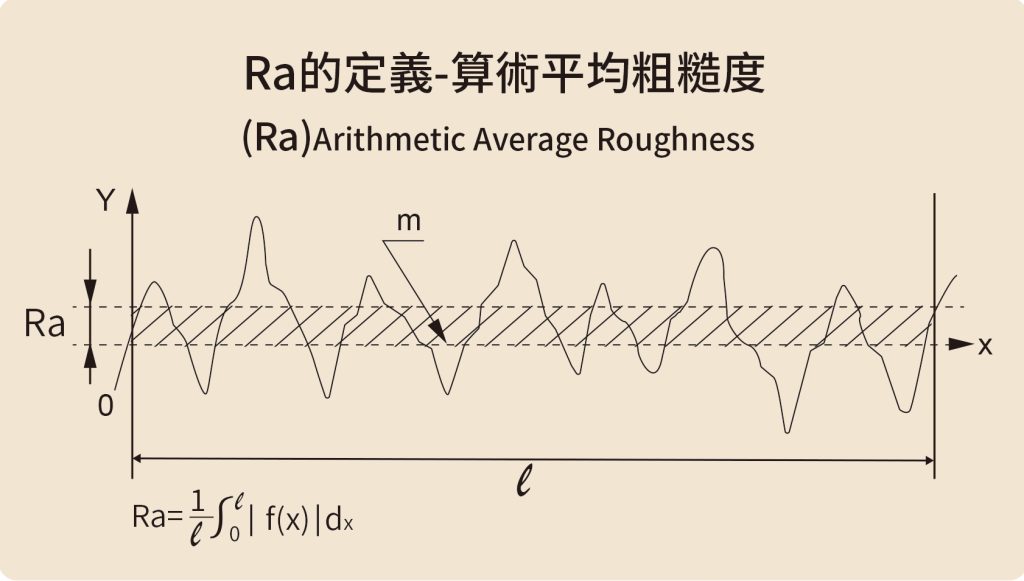
1. Ra – Arithmetic Average Roughness
Ra value is currently the most commonly used method worldwide to represent surface roughness, also known as Average Roughness. It is measured by tracing the surface profile and calculating the arithmetic mean of the absolute deviations of the peaks and valleys relative to the center line. The unit is micrometer (μm), where one micrometer equals one-thousandth of a millimeter, or one-millionth of a meter.
To better understand, you can imagine dividing the surface’s peaks and valleys into many tiny cross-sections. Ra is essentially the average height of these irregularities.
For example:
Ra 3.2 µm – Typical for general milling; visible tool marks remain.
Ra 0.8 µm – Achieved through fine turning or grinding; smooth to the touch.
Ra ≤ 0.2 µm – Mirror-finish level; common for optical components and mold surfaces.
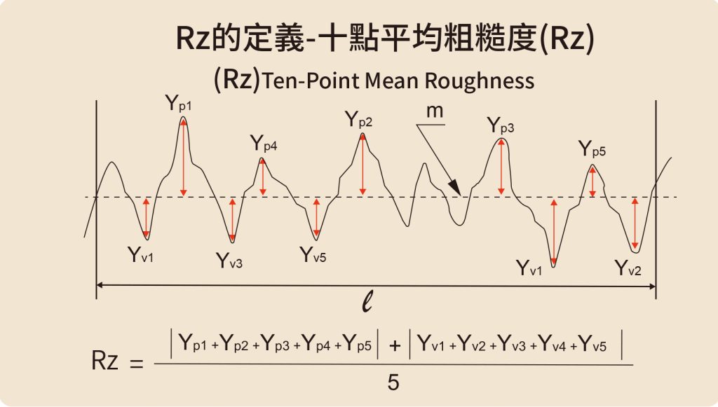
2. Rz – Ten-Point Mean Roughness
Ra provides an overall average and is less sensitive to isolated deep scratches, so it’s often paired with other metrics for stricter quality control.
Rz measures the average distance between the five highest peaks and the five deepest valleys over a measured length. It better reflects the overall amplitude of surface variations and is particularly effective for detecting deep tool marks, pits, or protrusions.
For example:
two parts may have the same Ra, but the one with a single deep scratch will show a significantly higher Rz value.
Rz is frequently used in automotive components, bearing seats, and sealing surfaces to prevent leakage, excessive wear, or operational instability.
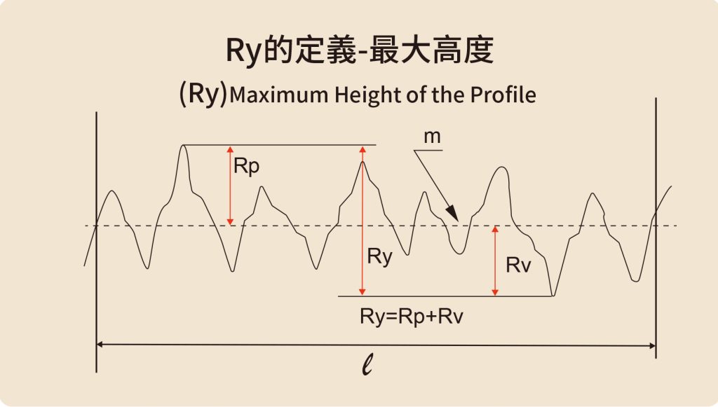
3. Ry – Maximum Height Roughness (Rmax)
Ry, sometimes called Rmax, measures the vertical distance between the highest peak and the deepest valley within the measurement length. It is highly sensitive to localized defects such as burrs, sharp scratches, or cracks, making it ideal for applications where even minor flaws can be critical
for example,
In the machining inspection of aerospace components, Ry is often used to check for sharp cracks that may affect fatigue life. In precision mold manufacturing, Ry helps detect local burrs or tool marks, preventing the finished surface from being scratched during use.
Why Ra is the Default on Engineering Drawings
Ra is favored because:
International recognition – Adopted by ISO, JIS, and ANSI standards.
Ease of measurement – Most roughness testers can quickly provide Ra readings.
Sufficient accuracy for most applications – Though it doesn’t capture extreme defects, Ra is adequate for general quality evaluation.
For critical components, engineers often specify Ra alongside Rz or Ry to ensure comprehensive quality control.
Typical Roughness Ranges and Corresponding Processes
| Roughness Range (Ra, µm) | Surface Condition | Common Machining Processes |
| 12.5–6.3 | isible tool marks | Rough turning, rough milling |
| 3.2–1.6 | Flat with fine marks | Fine milling, fine turning |
| 0.8–0.4 | Smooth, minimal marks | Grinding, fine turning, burnishing |
| 0.2–0.05 | Near-mirror finish | Ultrasonic polishing, nano-finishing, CMP |
| < 0.05 | True mirror finish | Ultrasonic polishing, nano-finishing, CMP |
This table acts as a “quality roadmap” for machinists, linking target roughness to the appropriate process.
Measurement Methods
Common inspection methods include:
Contact profilometers – A stylus moves across the surface to record profile variations.
Non-contact optical measurement – Laser or white-light interferometry for rapid, large-area scans, ideal for electronics or optics.
Comparator specimens – Physical reference blocks for quick, tactile assessment in the workshop.
表面粗糙度如何標示?
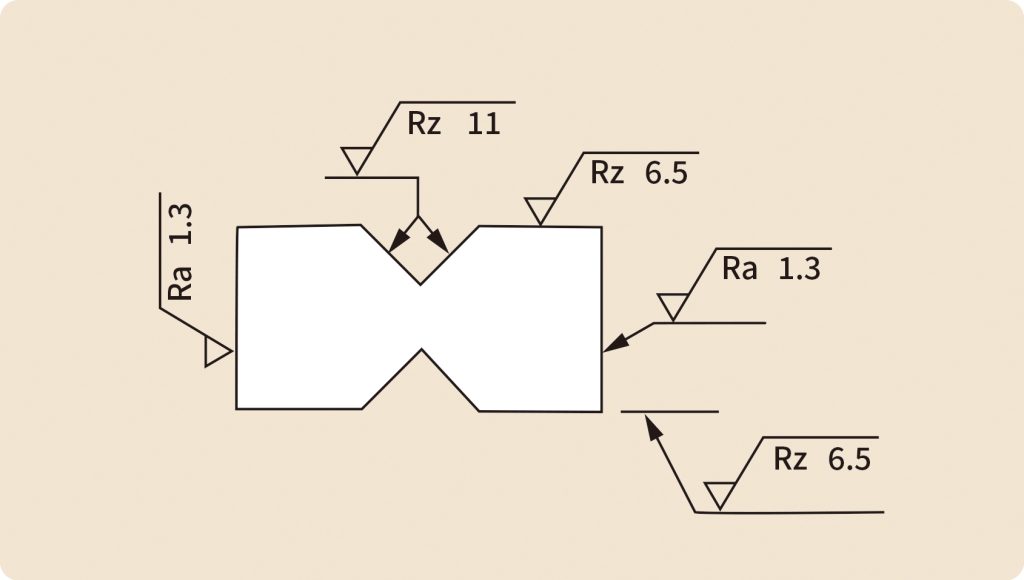
在工程圖上,表面粗糙度通常使用 ISO 1302 或 JIS B 0031 規範的符號。符號基本由「V」形斜線構成,可依需求增減附加資訊。
If the designer does not provide a specific indication, the roughness is generally defined by the drawing note, such as “Surface roughness not otherwise specified”, which serves as the machining reference.
一般會在零件的 特定加工表面 上加註粗糙度要求,避免整體加工成本過高。
Common Indications and Symbols of Surface Roughness::
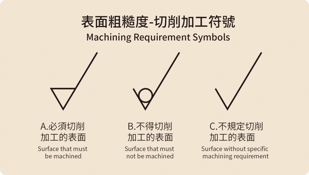
Machining Requirement Symbols (three types):
A. Surface that must be machined: Add a short bar at the top of the basic symbol, forming an equilateral triangle.
B. Surface that must not be machined: Add a small circle at the top of the basic symbol.
C. Surface without specific machining requirement: Use the basic symbol alone, without additional marks.
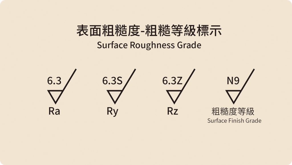
粗糙度標示
Surface roughness can be specified by Ra, Ry, Rz, or by roughness grade symbols.
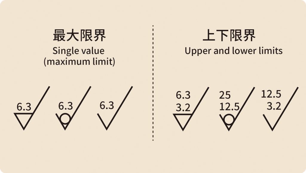
Surface roughness tolerance notation: For surface roughness, there are two ways to indicate limits: maximum limit and upper-lower limit notation.
- Single value (maximum limit): When only one roughness value is indicated, it represents the maximum permissible limit.
- Upper and lower limits: Indicated by two values written vertically, with the upper value being the maximum limit and the lower value being the minimum limit.
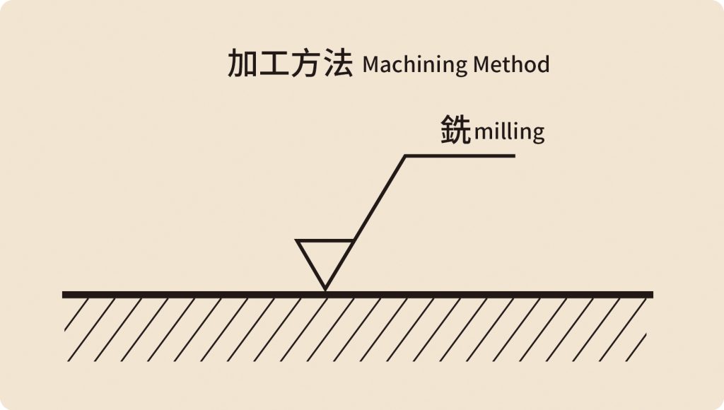
加工方法
If a specific machining process is required, a short bar is added at the end of the longer leg of the basic symbol, and the machining method is written above, such as: milling, turning, drilling, boring, reaming, etc.
Position of surface roughness symbols on drawing
The surface roughness symbol should be indicated outside the contour line of each machined surface, inside holes or slots, and at locations where it is most easily identifiable. As a general rule, the symbol should be placed upright and facing to the left. If the surface is inclined or the location is not suitable, a leader line may be used to indicate the symbol.
粗糙度為何重要?它決定零件的性能與壽命
In manufacturing, small details often have outsized consequences, and surface roughness is a prime example. It impacts not only appearance but also lubrication, sealing, fatigue resistance, and overall mechanical stability.
Automotive & Aerospace – Excessive roughness can cause poor lubrication, overheating, noise, or premature failure. Overly smooth surfaces may also reduce lubricant retention, increasing friction.
Mold Making – Poor surface quality can lead to molding defects, demolding difficulties, and poor coating adhesion.
Medical Devices – Implants and surgical instruments require exceptional finishes to prevent bacterial growth, tissue damage, or wear-related failures.
Medical Devices – Implants and surgical instruments require exceptional finishes to prevent bacterial growth, tissue damage, or wear-related failures.
In the field of precision machining, differences in surface roughness often signify the level of quality. Even if dimensional tolerances are perfectly accurate, insufficient surface quality may compromise overall assembly performance or lead to unstable fits. For many machining companies bidding on international contracts, surface roughness is often one of the critical requirements in addition to dimensional and geometric tolerances.
From a cost perspective, controlling surface roughness is also closely tied to the optimal allocation of resources. While pursuing ultra-low roughness can improve quality, it also results in additional machining time, equipment wear, and inspection costs. Therefore, establishing reasonable roughness standards based on actual functional requirements is a challenge that design engineers and manufacturing personnel must consider together.
In summary, surface roughness not only affects the efficiency and safety of component operation but also determines the durability and stability of the overall system. For enterprises, enhancing surface roughness management capability is one of the key factors in improving process stability, reducing failure rates, and strengthening competitiveness.
表面粗糙度是製造工藝與品質的縮影
表面粗糙度雖然肉眼難以察覺,但在機械加工中,它卻是影響品質、效能與壽命的關鍵指標。它不只是用來評價外觀的數據,更反映出整體加工技術與設備能力。對製造業者而言,懂得如何控制粗糙度、選擇正確加工方式與刀具,才能達到品質與效率的平衡。對設計端而言,合理規劃粗糙度要求,也能避免不必要的加工成本。無論是初學者還是專業人士,理解並重視表面粗糙度,就是邁向高品質製造的第一步。